 Produuz.it Docs
Appearance
Panel Sides and Coordinates
produuz.it uses one rule for the sides and the coordinates of a panel. The 3D viewer, the drawings, the lists and the machine files all start from it. This page explains the rule, how produuz.it reads it from your model, and which side each screen and each file looks from.
The rule in short
The rule
- Every panel has a front and a back. The front is the outside face and holds the positive zones. The back is the inside face and holds the negative zones. Zone 0 is the frame.
- X runs along the length of the panel, Y up its height, Z through its thickness, pointing towards the front.
- The origin is the bottom-left corner of the frame, seen from the front, on the outer face of the frame.
- All coordinates are in millimetres.
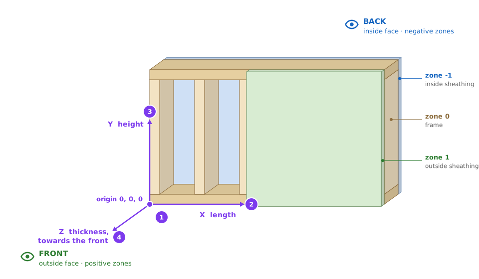
- Origin: the bottom-left corner of the frame seen from the front. It lies on the face of the frame that points to the outside, so the outside sheathing starts at Z = 0.
- X: along the panel, from left to right seen from the front.
- Y: up, from the bottom rail to the top rail.
- Z: through the thickness, from the inside to the outside.
Faces and zones
Every part of a panel has a zone: the layer it belongs to.
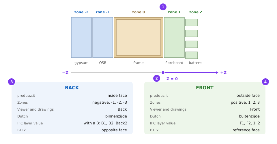
- Zone 0 is the frame: rails, studs and the other timbers of the structure.
- Z = 0 is the outer face of the frame. Positive zones have a positive Z, negative zones a negative Z.
- Negative zones are the layers of the inside face, counted outwards from the frame: -1 lies on the frame, -2 on top of -1, and so on.
- Positive zones are the layers of the outside face, counted the same way: 1 on the frame, 2 on top of 1.
A zone says which face a part is on, whichever side the panel was drawn from in your model. Zone 0 holds the frame only. Every part outside the frame has the zone of its face, battens, foils and cladding included: a batten or a foil takes the zone of the sheet it is fixed to, and the cladding the outermost zone of its face.
Battens and foils in zone 0
A batten or a foil left in zone 0 is taken as part of the frame. It shows on the frame drawing, and if your parsing setup categorises it as Wood profile it also moves the origin to its outer face.
Each face goes by several names, depending on where you meet it. They always mean the same face:
| Back | Front | |
|---|---|---|
| Face | inside | outside |
| Zones | negative: -1, -2, -3 | positive: 1, 2, 3 |
| 3D viewer and drawings | Back | Front |
| Machine settings | Inside, e.g. Inside Contour, Nailer zone 1 Inside | Outside, e.g. Outside Contour, Nailer zone 1 Outside |
| IFC layer value | holds a B: B1, B2, Back2 | F1, F2, 1, 2 |
| BTLx | opposite face | reference face |
| Dutch | binnenzijde | buitenzijde |
Interior and party walls have no outside. Choose one face as the front, give it the positive zones, and make the same choice for every panel of that type, so that identical panels get identical drawings and machine files.
When the company setting Zones from 10 are subzones is on, zones from 10 upwards belong to their main zone in the viewer: zone 12 is shown with zone 1, zone -25 with zone -2. See Company settings.
Where the sides come from
produuz.it reads the outside of a panel from the zones your model gives to its parts: a positive zone is outside, a negative zone is inside.
- IFC files: the zone is read with the Zone (layer) rule of your IFC Parsing Setup. A value that holds a
Bbecomes a negative zone; anything else stays positive. - BTLx files: BTLx layer numbers have no sign. The Positive side zones and Negative side zones rules of the parsing setup say which layers belong to each face.
WARNING
If your model writes the outside layers with a B, or a BTLx setup has no side rules, produuz.it takes the inside for the outside. Every view and every file of that panel is then mirrored. Check one panel in the 3D viewer after setting up a new exporter: Front must show the outside face.
How produuz.it places a panel
When a panel is analysed, produuz.it works out its axes from the frame and the zones:
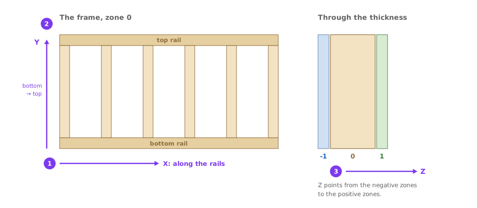
- X follows the longest top rail or bottom rail of zone 0.
- Y points from the bottom rail to the top rail.
- Z points from the negative zones to the positive zones. It is read from the plates of zones 1 to 3 and -1 to -3.
The origin is then the corner of the frame with the lowest X, the lowest Y and the highest Z. Only the wood profiles and the rails of zone 0 count for it. A sheet or a cladding board that overhangs the frame does not move the origin: where it overhangs the left or the bottom edge, it gets a negative X or Y.
produuz.it measures every panel in its own frame. Where the panel stands in the building is not used, so its drawings, lists and machine files are the same wherever it goes.
For this to work, a panel needs:
- at least one top rail or bottom rail in zone 0, as categorised by your parsing setup;
- at least one plate in zones 1 to 3 or -1 to -3. A panel with plates on one face only works too.
When one of them is missing, the panel analysis says that the orientation could not be found. Fix the parsing setup and analyse the panel again.
Floors and roofs follow the same rule. The front is the face of the positive zones, whichever way the panel lies in the building, and Y points from the member you categorise as bottom rail to the one you categorise as top rail. Give the positive zones to the top face, so that the front of a floor or a roof is the face seen from above. On a roof, categorise the lower member as bottom rail, so that Y points up the slope.
Best effort panel orientation
With the company setting Best effort panel orientation on, a panel whose orientation cannot be found from its rails and plates is placed from its geometry instead. The viewer and the drawings use it, but the front may come out on the wrong side. With the setting off, such a panel is shown in the coordinates of the model file. Machine files never use it: a panel without a proper orientation is left out of the file and listed in ERRORS.md. See Company settings.
Files from the Panel Designer
The Panel Designer works on the building: it frames every wall, floor and roof of the architect's model in its place, on its storey. produuz.it works in the factory, where a panel is a flat element built layer by layer. A Designer file carries both, so a panel goes from the building model to the factory floor with nothing to fix by hand.
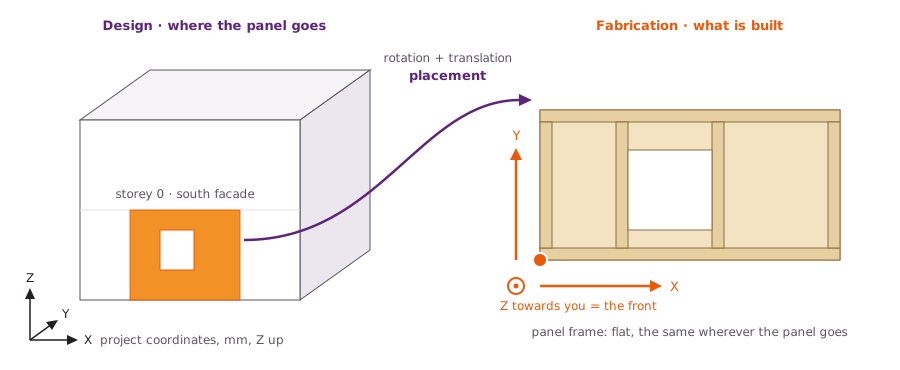
- In the Panel Designer the panel stands in the building, in project coordinates.
- In produuz.it the same panel lies flat, with the X, Y and Z of this page.
- The placement links the two. produuz.it builds from the flat panel, so the drawings, the lists and the machine files are the same wherever the panel goes.
What the file brings
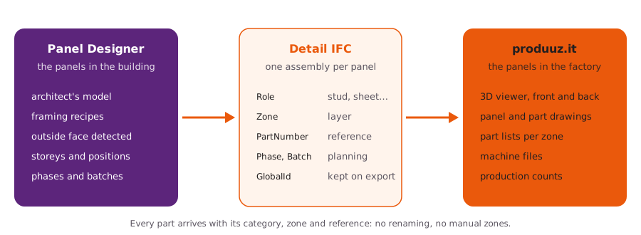
The Designer exports a detail IFC with one assembly per panel. Every part says what it is, which layer it is in and what its reference is, and every panel carries its phase and its batch. A parsing setup reads them one to one:
| In the Designer file | In produuz.it |
|---|---|
Role top_plate, bottom_plate | Top Rail Wood, Bottom Rail Wood |
Role stud, end_stud, jamb, sill, header, lintel and the other frame timbers | Wood profile |
Role extra | Extra Frame Wood profile |
Role sheet, drawn | Plate |
Role batten, service_batten | Wood Batten |
Role insulation | Isolated Area |
Zone | The zone of the part |
PartNumber | The part reference |
Material, Weight, Finish, Comments | The same part properties |
Phase_name, Batch, Assembly_name | The phase, the batch and the design of the panel |
What that gives you:
- The outside is found for you. The Designer detects the outside face from the architect's model and puts the positive zones on it. In the 3D viewer, Front shows the facade, and every drawing and machine file starts from the right face.
- No zones to type. Every sheet comes with its zone, counted outwards from the frame as produuz.it expects.
- The same panel, the same drawings. produuz.it measures every panel flat, so two panels built the same way get the same drawings and machine files, whichever facade they go on.
- Export again without losing anything. The Designer keeps the GlobalId of every panel and every part when you export again, so produuz.it recognises the units it already has. See How each file counts.
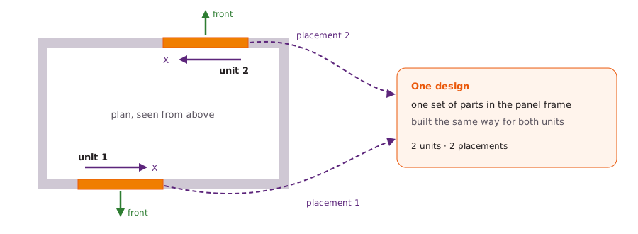
Two identical panels on opposite facades: two units in the building, built the same way in the factory.
Reference side
Keep the reference side of the framing recipes on outside, the default. With inside, the positive zones are the inside layers and Front shows the room side.
The front and the back
Seen from the back, a panel is the front view mirrored. The same physical corner moves from one side of the picture to the other.
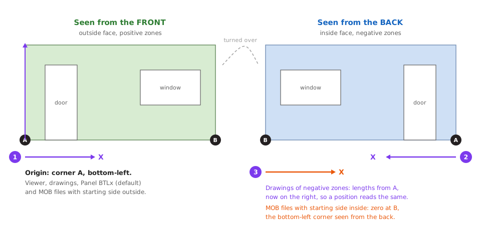
- Seen from the front, the origin is corner A, bottom-left, and X runs to the right.
- Drawings seen from the back keep measuring from corner A, which is now at the bottom-right. A length reads the same on the front and on the back drawing.
- MOB files with starting side inside measure the panel from the back, with their zero at corner B: the bottom-left corner seen from the back.
Drawings and MOB files on the inside face
A length on a drawing of a negative zone is measured from corner A. An X in a MOB file with starting side inside is measured from corner B, the other end of the panel. Both are correct; they start from opposite ends.
Which side each screen and file looks from
| Where | Seen from | Measured from |
|---|---|---|
| 3D viewer | Opens on the front. Front and Back buttons turn it. | — |
| Panel drawings | Zone 0 and positive zones from the front. Negative zones from the back. A custom branch from the back only when all its parts are in negative zones. | Corner A: bottom-left on a front drawing, bottom-right on a back drawing. Heights from the bottom. |
| Part drawings | Each plate from the face that points away from the frame. | The part's own corner. |
| MOB v1 and MOB v2 | The Production starting side of the station that owns zone 0. Inside, the default, reads the panel from the back; outside from the front. | Inside: corner B. Outside: corner A. The Machine zero of the machine setup can move it to the other end. |
| Panel BTLx | The Starting side of the job, outside by default. | Outside: corner A. Inside: corner B. X = 0 at the left edge of the frame, Y = 0 at its bottom edge. |
| MTF | Always from the back. | Corner B. |
| Part files: BTL, BTLx parts, BVX, Generic Wood CSV, Ardis, XCS, CIX, DXF, DSTV | Each part on its own, in the position the machine needs. | The part's own corner. The panel coordinates are not used. |
A plate has one reference and one drawing, whichever face it is mounted on. Two plates with the same shape in zone 1 and in zone -1 are the same plate in the lists. If they must be told apart, model them mirrored.
Production starting side
The starting side says which face of the panel is clad first on a panel line:
- Inside (default): the frame is built, the inside face (negative zones) is clad, the panel is turned over, then the outside face (positive zones) is clad.
- Outside: the other way round.
It also decides which face the MOB file measures the panel from. The value of the station that owns zone 0 applies to the whole line. See MOB v2.
Some machine settings change the side or the corner for one station only: Switch direction X-axis, Switch direction Y-axis and Machine zero on the Mobi One, and the face inversions on the Frame Station. Leave them at their defaults unless one station comes out mirrored. See Mobi One and Frame Station.
When a panel comes out wrong
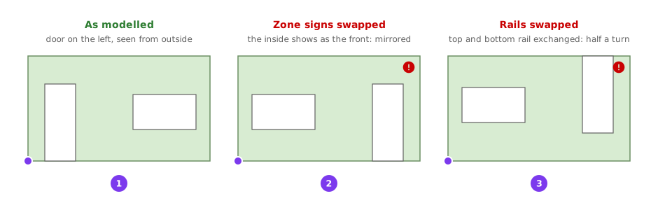
- As modelled: seen from the front, the panel looks as it does from outside the building.
- Zone signs swapped: the inside layers have positive zones and the outside layers negative ones. The front shows the inside face, and the panel is mirrored left to right everywhere.
- Rails swapped: the top rail is categorised as bottom rail and the other way round. Y points down, so X turns too: the panel is turned half a turn.
| What you see | Where to look |
|---|---|
| The viewer's Front shows the inside face | The zones of the IFC export (F/B) or the BTLx side rules. See Zone (layer). |
| The panel is upside down and mirrored | The Top rail and Bottom rail categories of the parsing setup. |
| The origin is on the face of the battens or the cladding, not on the frame | Battens or other layers in zone 0. Give them the zone of their face. See Faces and zones. |
| The analysis says the orientation could not be found | A top or bottom rail in zone 0, and a plate in zones 1 to 3 or -1 to -3. |
| The panel is right in the viewer, but one machine file is mirrored | The machine settings of that station. See When a file comes out mirrored. |
| A back drawing and a MOB file give different X values | Expected with starting side inside: they measure from opposite ends. See The front and the back. |
Checklist for a new exporter
- The frame is zone 0, and nothing else is.
- The outside layers are positive zones (
F1,F2, or1,2) and the inside layers negative ones (B1,B2, or-1,-2), counted outwards from the frame. The sign follows the face, whichever side the panel was drawn from. - Battens, foils and cladding have the zone of their face.
- Floors and roofs have their positive zones on the top face. Interior walls use the same front for every panel of a type.
- The top and bottom rails of the frame are categorised as such in the parsing setup.
- For BTLx, the parsing setup declares the positive and negative side zones.
- In the 3D viewer, Front shows the outside face, with the bottom rail at the bottom.