 Produuz.it Docs
Appearance
Production Lines
A company must have at least one production line defined in the system.
Production Settings is a menu group with three views. Production lines holds the lines and their stations. Machine settings holds the machine setups. Automations holds the action triggers and the setups they run: machine files and drawings.
File generation templates are not here — they live in File settings, under the Files section of the menu. See Reports.
The Production lines view
Each production line is a row: a header with its name, what it builds, its counts and its actions, and below it the cards of its stations in the order the line runs them.
Rows can be collapsed with the arrow on the left. They all start open, and the ones you collapse stay collapsed the next time you open the view.
Lines are grouped by what they build: modules first, then assemblies, then parts. A line that builds more than one of these appears once, under the largest one. Lines with an unrecognised tipo go to a last group, Other.
Machine settings are grouped by machine type. Licensed types show how many setups you have out of your licensed maximum. Each card lists what uses the setup — stations and production lines alike — and warns only when nothing does.
Working with stations
At the end of every line there are two tiles:
- New Production Station creates a station and adds it to that line.
- Add existing station lists every station that is not already in the line, including the ones with no line at all.
Reordering is done by dragging a station card by its handle. The new order is saved as soon as you drop the card. You cannot drag a card from one line into another: to move a station, add it to the new line and then remove it from the old one.
A station can belong to several lines at once. It then gets a card in each of them, marked SHARED, and its cards list the lines it is in. It is the same station in all of them, so editing it from any line changes it everywhere. Its position, on the other hand, belongs to each line separately.
Stations that belong to no line are listed at the end of the view, under No production line. This is normal — a station can be created or left without a line — and it is the only place where you can reach them.
Deleting a station asks what you mean:
- Remove from this line takes it out of that line only. The station stays, and if it was in no other line it moves to the No production line group.
- Delete removes the station from every line and loses its checklist. This cannot be undone.
The machine of a line
A line can name the machine it runs on. Tick Line machine in the line form and pick one.
There are two ways to record it, and both are fine:
- On the line. Use this when the line is one machine — a saw line, a plates cutter. There are no stations to hang it on.
- On a single station. Use this when the line has one station and the machine belongs to it. Nothing changes for the lines you already set up this way.
Either way, the machine's name appears on the line header, next to what the line builds. When it was read off a station rather than set on the line, it is shown in grey italics, so you can tell at a glance where it came from.
If a line has a machine and one of its stations has another one, the form says so. The line's machine is the one that counts for the line. It is a notice, not an error: the form saves either way.
A line with several stations that each have their own machine — an automated panel line — has no single machine to name. Give it one by creating a MOB2 production line machine setup and picking it as the line machine. That setup exists to hold what belongs to the whole line rather than to one of its tables; it has no settings yet, and each one will appear as it starts being used.
Picking a machine setup
Both machine pickers — the one on a station and the one on a line — put the setups that usually go there first, and everything else under Other machines. Nothing is hidden: if you pick a setup from the second group, the form tells you where it normally goes and lets you carry on.
When you create a machine setup, the Model list is grouped the same way, by where that kind of machine goes:
- Production line settings — holds what belongs to a whole line. Today that is H&M MOB2 production line.
- Machine stations — goes on a station of a line.
- Standalone machines — machines you send generated files to: saws, cutters, profilers. These can also be named as the machine of a logistics line.
Most models have no settings of their own: a cutter is configured by the options of the file it is sent, not by a form here. When that is the case the form says so instead of showing you an empty one.
The machine configuration file
Some machine models accept the machine's own configuration file (XML or INI). Uploading it fills the parsed params, shown next to the uploader as read-only JSON: the top level is open and each block can be expanded. The parsed params include a parsed entry with the date and time the file was read, so you always know how old the configuration is.
Automations
Two things live in this view, and one uses the other: the setups, which say how something is generated, and the action triggers, which say when.
Machine file setups
A machine file setup is a saved MOB v2 setup: how the machine file is built — operations, nailing, shifts and layers.
Running one takes a panel design, builds the machine file for every station of every production line, and sends it to the machines. There is no report and no download in between, and there is no way to limit it to a single line.
You use a machine file setup from two places:
- an action trigger, so it runs on its own, and
- the AUTO MOB v2 file type, to run it by hand on the panels you pick.
Drawing setups
A drawing setup is a saved set of drawings. It decides:
- Views to generate — front, top, section, back, bottom, right.
- One drawing per zone — an extra drawing per zone of the panel, with the parts of the other zones drawn as a dashed outline.
- Include the framework (zone 0) — the woods-only layer, drawn as FRAMEWORK.
- Positioning origin — where the parts are placed from.
Running one takes a design and writes the drawings straight into the design's files, marked as generated. There is no report in between.
You use a drawing setup from two places:
- an action trigger, so it runs on its own, and
- the Launch action button on the designs and multipanel groups tables, to run it by hand. Here the setup is optional: without one you get the default views (front, top, section, plus one per zone).
The design's drawings card shows whether a run is working or failed, and warns when a newer IFC arrived after the drawings were made, marking the outdated ones. Generate the drawings again from the same button; Clean deletes the generated ones without touching the drawings you uploaded yourself.
Action triggers
An action trigger runs something on its own when an event happens in production, with nobody clicking anything. It reads as three steps:
- When this happens — the event. Today the only event is a design finishing its analysis.
- Only if — an optional condition on a field of the design (
name,tipo, or a key of its client data), matched as a full word, a prefix, or "contains". Leave it empty and the trigger applies to every design. - Then do this — the action, and the setup it runs with:
- Generate MOB v2 files and send them to the machines, with a machine file setup.
- Generate the drawings of the design, with a drawing setup — or none, for the default views.
WARNING
A trigger runs for every design that matches, each time it finishes its analysis. Use Only if to narrow it down before turning one on in a busy project.
The production line (PL) itself has the following fields:
- Name: A name to identify the PL.
- Tipo: Assembly or module categories that the PL can produce.
- Client IDs: An optional list of external identifiers used to link the production line to external systems (e.g. ERP or planning software). Multiple IDs can be added when the line needs to be matched from more than one external source.
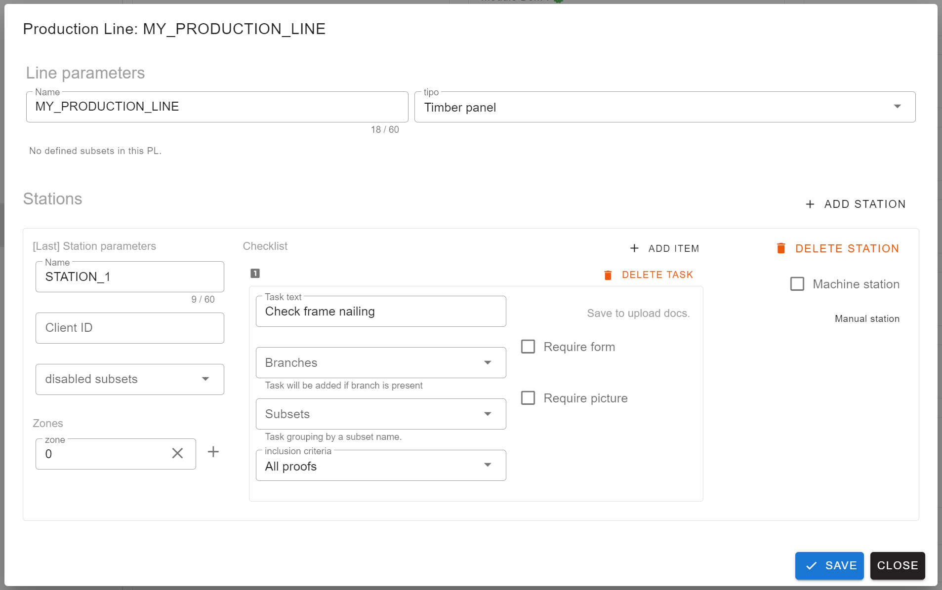
Production lines (PLs) are expected to have at least 1 station. Stations represent steps in the production process.
Stations fields:
- Name: Simply a name.
- Clien ID: Client ID of the station, usually comes from an external application that the client want to link.
- Zones: What zones are expected to be produced in this stations. For example add 0 for a typical framing station. If two stations in the same production line share a zone, a warning is shown at the top of the line, naming the duplicated zone and the stations it is in.
- Machine: If the station is marked as a "machine station", then you have to define a machine setup that will be linked to this station. For example: A MOBI-ONE station defined in "Machines".
As a last nested item, we have checklist items for each station. This will be entries for the production users to be checked in the production interface ("the viewer").
Checklist fields:
- Task text: The text that will be shown to the production user.
- DOCS: A feature that allows the company to add documentation specific to the task, such as guidelines, specifications, ...
- Branches: If empty, this is ignored. If filled, selected branches will be searched in the constructible, to see if it's needed to be added. The station zones are also considered. If station zones exist, then the branch needs to be present in the station zones. Only then the checklist task is included.
- Inclusion criteria: All means all checklist will get this task. 1/n will be added in 1 checklist each n checklists started. 1/n randomized will do the same but at a random pace.