 Produuz.it Docs
Appearance
MOB v2 Machine File
Beta — under review
This page is new and is still being checked against the machines. It may be incomplete or contain mistakes, so do not rely on it alone for production settings. If something here does not match what you see, tell us.
A MOB v2 file tells an H&M panel line what to do with one wall or floor panel: where the frame pieces go, where to nail, screw, mill, saw, drill and glue, and on which face. produuz.it writes it from the IFC model of the panel and from how your production line is set up.
It is read by the Mobi One V2, the Frame Station V2, the Robobrick and the Isolation machine. One file covers every station of the line: the frame, the inside face and the outside face of the panel are all in the same file.
How a file is made
Three things decide what ends up in the file: the zones of the parts in the model, the stations of the production line, and the machine setup of each station.
Zones and faces
Every part of the panel has a zone, read by your IFC Parsing Setup.
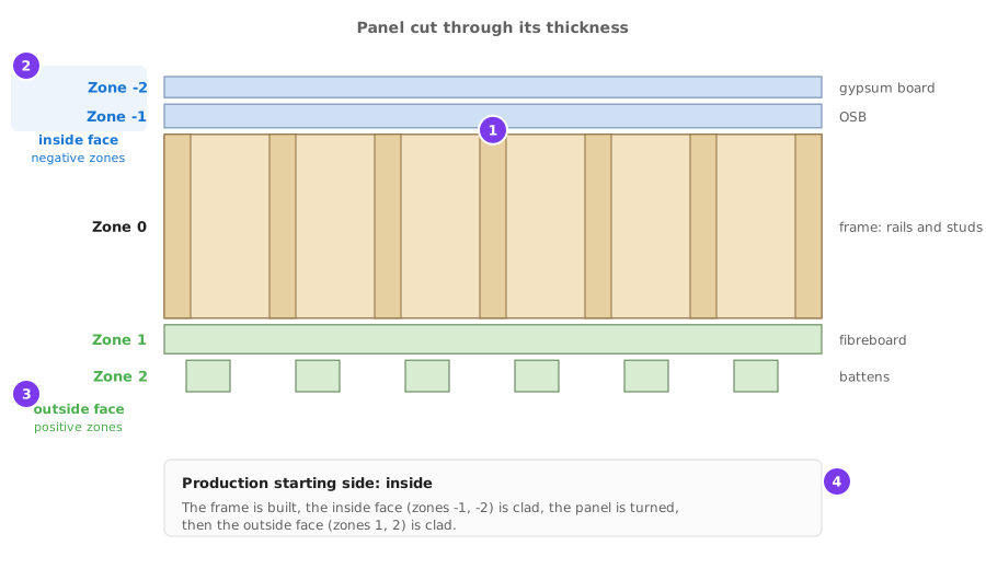
- Zone 0 is the frame: rails, studs and the other frame woods.
- Negative zones are the layers of the inside face, counted outwards from the frame: -1 on the frame, -2 on top of -1.
- Positive zones are the layers of the outside face, counted the same way.
- The Production starting side says which face is clad first. See General.
The outside face is the front of the panel in the 3D viewer and on the drawings. See Panel Sides and Coordinates.
A part with no zone is not produced by any station, so it never reaches the file.
From a production line to one file
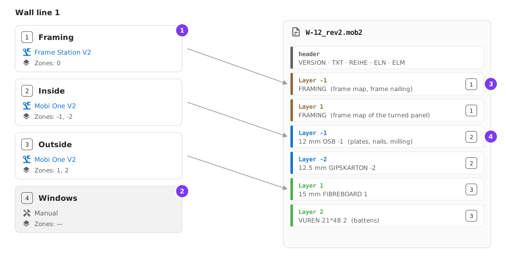
- Each machine station produces the zones listed in its Zones field, with its own machine setup and its own job options. Stations are taken in the order of the line.
- Manual stations are skipped: they have no machine and write nothing.
- The frame layers come first in the file, for the frame and for the turned panel.
- Then the layers of each station follow, in station order. Within one station the inside zones come first, then the outside ones. A zone with battens gets its batten layer just before its plate layer.
Rules that follow from this:
- A zone belongs to the first station that lists it. If two stations list the same zone, only the first produces it. The line form warns about it: Please note that you have the zone 0 in stations: …
- A zone that no station lists is not produced, and nothing warns you. Check the Zones of your stations against the zones your parsing setup gives.
- The station that owns zone 0 decides for the whole line: its Production starting side and Shift mode, and which operation drawings are made (the SVG Drawings switches of its machine setup). Give zone 0 to exactly one station.
- Every machine station must have one of the MOB v2 machines listed above. Put saws and plate cutters on their own lines, and put the H&M Mobi One V2 Production Line setup on the line itself, never on a station. See The machine of a line.
- Two stations must not share one machine setup. Create one setup per station, even when the machines are identical.
What the machine configuration file decides
Each Mobi One, Frame Station, Robobrick and Isolation setup takes the machine's own configuration file (XML), uploaded in the Machine file tab of the setup. It tells produuz.it what the machine has:
- Which tools exist. The tool fields of the report form only offer the tools the file declares. See Tool IDs.
- Which operations are possible. Plate nailing, screwing, milling, sawing and gluing are only written when the machine has the unit for them. Frame nailing needs a framing unit.
- Flooring. A file with flooring stations turns the frame layer into flooring clamp commands instead of frame nailing.
- Sizes used by trimming: the maximum width, and the maximum length when the setup does not set its own.
- Machine zero, when the setup's Machine zero is File info. See Mobi One.
Upload the configuration file first
Without it the report form offers almost no tools, and the file cannot be generated: the panel fails with an error.
Creating the file
- Open Production files in a project and press New file.
- Pick MOB v2 Machine File as the Report Type.
- Pick the Production line. One Station Job Options block appears for each station with a MOB v2 machine, filled in with the default job options of its machine setup.
- Change the options you need for this file. They are explained below.
- Select the panels and press Submit.
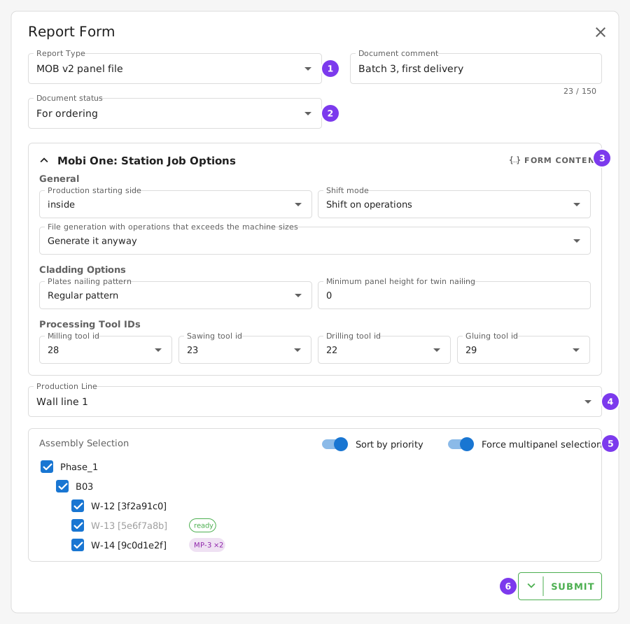
- MOB v2 Machine File as the report type.
- The document status.
- One Station Job Options block per machine station.
- The production line the file is made for.
- The panels to include.
- Submit.
The same file type can also be generated from a generation template, and on its own when a design finishes its analysis, with an action trigger. The Mobfile Generator makes MOB v2 files from files that are not in a project.
What is in the file
A MOB v2 file is plain text, one command per row, each row ending in ;.
Header
| Row | What it holds |
|---|---|
VERSION | Always 3.00. |
TXT | Comment rows: design name and id, project, the machine zeros, the shifts and the date the file was made. |
REIHE | The production starting side, inside or outside. |
ELN | The design name. |
ELM | Length, height and total thickness of the panel, in mm. |
Layers
The rest of the file is a list of layers:
Layer, <zone>, <name>, <type>, <x shift>, <y shift>, <length>, <height>;
... commands ...
End Layer, <zone>;
Layer, <zone>, <name>, <type>, <x shift>, <y shift>, <length>, <height>;
... commands ...
End Layer, <zone>;The name is FRAMING for the frame, and the plate thickness, material and zone for a plate layer (12 mm OSB -1). The shifts are only filled in with Shift on layers. See Shift mode.
Commands
| Command | What it does |
|---|---|
BR, TR, HC, VC, AC4 | The frame map: bottom rail, top rail, horizontal pieces, vertical pieces (studs), and pieces with angled cuts. |
NRY | Frame nailing: where the rails are nailed into each stud, and how many nails. |
NRYA | Nailing through extra rails into the frame. |
FLOORING, FT1…FT6 | Flooring clamps, instead of frame nailing, when the machine has flooring stations. |
OS | A plate: its size, position and material. |
BA | A batten. |
NRZ | A plate nail line with one head. |
NRZ1 + NRZ2 | A plate nail line split between two heads that nail at the same time. |
BNRZV | A batten nail line. |
SCW | Screwing. |
PSG + PP | A milling or sawing path: PSG starts it, each PP is a point. |
MP | A round hole or a drilling. |
ELPS | An elliptical hole. |
GLUE, TWINGLUE | Glue lines, with one head or two. |
MSN, MSNGLUE | Bricks and their glue (Robobrick). |
INS | Insulation shots (Isolation machine). |
An example
The start of a real file, shortened:
VERSION       3.00;
TXT # MOB2 Conversion by Produuz.it;
TXT # Design name: TEST1;
TXT # Machine Zeros / Inside: Right Top / Outside: Right Top;
TXT # Shifts / X in: 0  /  Y in: 0  /  X out: 0.0  /  Y out: 0.0 / X RB: 0  /  Y RB: 0;
REIHE     inside;
ELN      TEST1;
ELM   4078,  2630,    69,     1,     0,     0;
Layer,     -1,   FRAMING,     1,     0,     0,  4078,  2630;
BR   1351,    44,    44,     0,     0,        01,H214 VUREN-C 44.0x44.0,     0,     0;
TR   1351,    44,    44,     0,  2586,        01,H454 VUREN-C 44.0x44.0,     0,     1;
VC   2542,    44,    44,  1307,    44,        01,H216 VUREN-C 44.0x44.0,     0,    11;
End Layer,     -1;
Layer,     -1,12 mm FERMACELL -1,   110,     0,     0,  4078,  2630;
OS   1200,  2627,    12,   148,     3,     0,12.5 FERMACELL 1200x2627,    44,     1;
PSG;
MP    347,  2480,  30.0,    12,  2228,    56;
End Layer,     -1;
VERSION 3.00;
TXT # MOB2 Conversion by Produuz.it;
TXT # Design name: TEST1;
TXT # Machine Zeros / Inside: Right Top / Outside: Right Top;
TXT # Shifts / X in: 0 / Y in: 0 / X out: 0.0 / Y out: 0.0 / X RB: 0 / Y RB: 0;
REIHE inside;
ELN TEST1;
ELM 4078, 2630, 69, 1, 0, 0;
Layer, -1, FRAMING, 1, 0, 0, 4078, 2630;
BR 1351, 44, 44, 0, 0, 01,H214 VUREN-C 44.0x44.0, 0, 0;
TR 1351, 44, 44, 0, 2586, 01,H454 VUREN-C 44.0x44.0, 0, 1;
VC 2542, 44, 44, 1307, 44, 01,H216 VUREN-C 44.0x44.0, 0, 11;
End Layer, -1;
Layer, -1,12 mm FERMACELL -1, 110, 0, 0, 4078, 2630;
OS 1200, 2627, 12, 148, 3, 0,12.5 FERMACELL 1200x2627, 44, 1;
PSG;
MP 347, 2480, 30.0, 12, 2228, 56;
End Layer, -1;Where the operations come from
- Plate nail lines come from the nail line elements drawn in the model, recognised by the Plate Nail Lines rule of your parsing setup. Their spacing is the model's Nail/Screw CTC when it has one, otherwise the Default value for CTC in plates nailing of the machine setup, otherwise 150 mm. The machine spreads the nails evenly over the line.
- Frame nailing follows the nailing matrix of the machine setup when Use Custom Matrix pattern is on, and an automatic rule otherwise. Frame nails drawn in the model always win.
- Holes in the plates are found on their own, from the openings in the plate outline, even when the model has no milling. Milling, sawing and drilling elements of the model are added to them.
- Lockout areas in the model cut the nail lines that cross them.
Job options
These are the options of a Mobi One V2 station, with the labels of the report form. Frame Station V2, Robobrick and Isolation have their own, listed at the end.
General
| Option | Choices | Default |
|---|---|---|
| Production starting side | inside, outside | inside |
| Shift mode | No shift, Shift on layers, Shift on operations | Shift on operations |
| File generation with operations that exceeds the machine sizes | Trim operations up to max size, Do not generate the layer, Generate it anyway | Generate it anyway |
Production starting side says which face is clad first, and so how the panel is measured and in which order the layers come. The value of the station that owns zone 0 applies to the whole line.
Shift mode corrects for how the panel lies against the stops of the table.
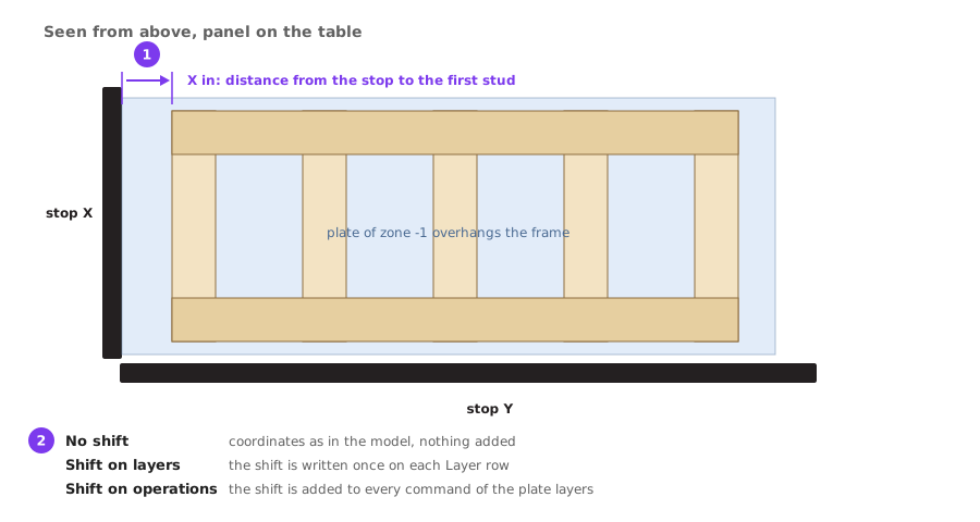
- The panel is pushed against the X and Y stops. When the outermost stud or rail is set back from the edge, because a plate overhangs it for example, the frame is not where the model says. The shift is that distance. The stop height used to decide what touches the stop is the Blocker Height X / Y of the machine setup.
- The three modes decide where the shift goes. The shifts are always printed in the header, in the Shifts row.
File generation with operations that exceeds the machine sizes decides what happens when an operation reaches past what the machine can do:
- Generate it anyway writes every operation as it is.
- Trim operations up to max size leaves out the operations that start beyond the machine size, and shortens the ones that cross it. Studs beyond it get no frame nailing.
- Do not generate the layer leaves out the frame nailing beyond the machine size. At the moment the plate layers are written as with Generate it anyway.
The machine size is the Max Wall Length for X axis of the machine setup for the length, and the maximum width of the configuration file. When the machine setup leaves its length empty, the length of the configuration file is used.
Framing
| Option | Default |
|---|---|
| Use Custom Matrix pattern | Off |
On: frame nails follow the Nailing matrix by beam size of the machine setup, with its nail columns and its per-class matrices. Off: an automatic rule places them from the paddings and the minimum distance between nails of the machine setup. See Mobi One.
Cladding options
| Option | Default |
|---|---|
| Plates nailing pattern | Regular pattern |
| Minimum panel height for twin nailing | 0 |
Plates nailing pattern: nail lines with one head are always put in the shortest order, whatever the option. Lines with two heads follow the regular order, unless the option is Twin Nailing Optimized (BETA). With it, the plate nailing of every zone with a twin nailer is planned from scratch. First, as in the regular order, the bottom row and the top row are each joined into one line, and the lines along a stud are joined into one when the gap between them is 250 mm or less. Then each nail line in the lower half of the panel is matched with a line in the upper half, and the two heads nail them together. Two lines on the same stud are nailed together even when their lengths differ, each head stopping at its own end. Horizontal lines that only partly match are nailed together where they overlap, and the rest is nailed by one head. A stud that runs through the middle of the panel is split in two halves, one per head. Lines with no partner (sills, short pieces, sloped lines) are nailed by the head of their half, fitted in between. The two heads must stay at least 500 mm apart, so lines closer than that are never paired. The order of the whole zone is then chosen to keep the machine travel short: the route sweeps the panel along its length and only takes a shortcut where it saves travel. If the optimizer fails on a zone, that zone falls back to the regular order and the file says so. Floors built on the frame station keep the regular order.
Minimum panel height for twin nailing: panels lower than this height (mm) are always nailed with one head, the first one, even when a twin nailer is set. 0 turns it off.
Mill and saw directions
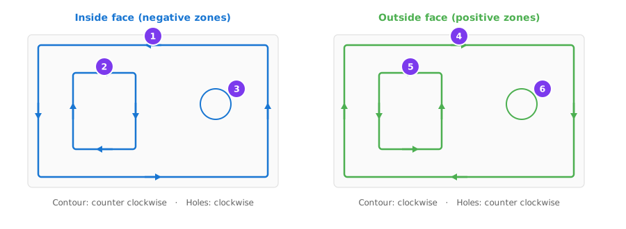
- Inside Contour: the outer edge of the plates on the inside face. Counter clockwise by default.
- Inside Holes: holes with straight edges on the inside face. Clockwise by default.
- Round and elliptical holes keep their own direction and do not follow the Holes setting.
- Outside Contour: the outer edge on the outside face. Clockwise by default.
- Outside Holes. Counter clockwise by default.
- Round holes, as in 3.
The four (Saw) settings do the same for sawing paths. A form saved before they existed takes the milling directions.
Tool IDs
The tool fields only list the tools that the configuration file of the machine declares. A tool missing from the list is missing from the file: upload the configuration file again after the machine changes.
Plates Nailer Tool ID is set per zone and face, for zones 1 to 3.
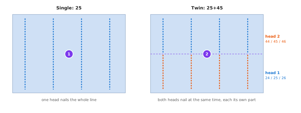
- One number (
24,25,26on the left carriage,44,45,46on the right) nails the whole line with that head. - Two numbers (
25+45) split each line between two heads that nail at the same time: the first takes the lower part of the line, the second the upper part. This is only offered when the machine has both heads.
Two more choices take the tool from the model, from the tool id of each nail line:
- Single nailing from model uses one head per line, the one the model names.
- Twin nailing from model uses the pair of the tool named by the first line of the zone, for every line of that zone.
On a machine with twin nailers the right-hand heads (44, 45, 46) are not offered alone.
| Field | Choices | Default |
|---|---|---|
| Plates Nailer Tool ID zone 1–3 Inside / Outside | the nailers of the machine, their twin pairs, Single nailing from model, Twin nailing from model | 5 |
| Screwdriver Tool ID zone 1–3 Inside / Outside | 0, 1 | 0 |
| Battens Tool ID zone Inside / Outside | the nailers of the machine | 25 |
| Milling tool id | 28, 48 | 28 |
| Sawing tool id | 23, 33, 43 | 23 |
| Drilling tool id | 22, 42 | 22 |
| Gluing tool id | 29, 49, 29+49 | 29 |
At the moment the screwer follows the nailer of the zone, drilling always uses tool 22, and glue lines always use tool 29, or 29 and 49 for twin gluing. Twin gluing falls back to one head on panels lower than the Min height to use twin gluing of the machine setup.
Default job options
Each machine setup has a MOB v2 panel file tab with its own default job options. They fill the station's block when you pick the line in the report form, and they are also used by generation templates. Set them once there, and change them in the report form only for the file you are making.
Frame Station V2
A Frame Station builds the frame only, so its block is shorter: Production starting side, Shift mode, File generation with operations that exceeds the machine sizes, Frame layer orientation, Use Custom Matrix pattern, Minimal framing CtC, Frame gluing tool id, Frame sawing tool id and Max distance between glue lines for joining them. It usually owns zone 0, so its starting side and shift mode apply to the whole line. See Frame Station.
Robobrick
| Option | Choices | Default |
|---|---|---|
| Max distance between Glue lines for joining them | mm | 100 |
| UUID Export mode | IFC GID (base64) (produuz.it standard), IFC GID converted to canonical UUID v4 | IFC GID (base64) |
UUID Export mode decides how the id of each brick is written. Use optimized mode is also shown and has no effect at the moment. See Robobrick.
Isolation machine
Production starting side, Shift mode, and Export Isolation as CSV, which adds a CSV file of the insulation shots next to the MOB v2 file. See Isolation machine.
Output
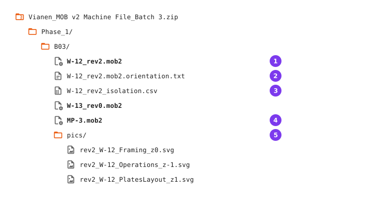
- One
.mob2file per design, named after the design and its revision, in a folder per phase and batch. Several panels of the same design share the file. .orientation.txt: what each station used to place the panel: its zones, its machine zero, its starting side and orientation settings, and which station owns zone 0. Open it when a file comes out mirrored._isolation.csv, when an Isolation station has Export Isolation as CSV on.- A multipanel group gets one file named after the group, with no revision. See Multipanel Groups.
pics/: the operation drawings, one per zone and kind: framing nails, operations (nailing, milling and drilling, with the order and the nail counts), plates layout, battens, bricks, insulation and the nail context. Which ones are made is set by the SVG Drawings switches of the machine setup that owns zone 0.
The operation drawings are also added to each panel, behind the MOB2 button of the viewer. Each new report replaces them.
The .mob2 files stay with the report: download them from Production files.
If a panel fails, it is left out of the ZIP and the report still finishes. The reason is written in ERRORS.md inside the ZIP, and whoever launched the report gets one notification saying how many problems it has. The same happens when the nailing or glue lines optimizer fails and the regular pattern is used.
When something is wrong
| What you see | Look at |
|---|---|
| The panel is missing from the ZIP | The message you got. Common causes: the model has no bottom or top rail, the machine setup has no configuration file, or a station of the line has a machine that is not a MOB v2 machine. |
| A face or a zone is missing | The Zones of the stations. A zone listed on no station is not produced. |
| A zone is produced by the wrong station | Two stations list it: the first one in the line wins. |
| No plate nailing | The model has no nail line elements, or the configuration file declares no nailers. |
| A tool is not in the list | The configuration file does not declare it. Upload the current file in the Machine file tab. |
| Twin nailing came out with one head | The panel is lower than Minimum panel height for twin nailing. |
| Frame nailing replaced by flooring commands | The configuration file declares flooring stations. |
| The panel is mirrored or starts on the wrong face | The .orientation.txt file, the starting side of the station that owns zone 0, and the orientation settings of the machine setups. See Mobi One. |
| Holes milled that the model does not mill | Holes are found from the openings of the plates. |
| Small round holes missing | Holes smaller than the Minimal milling radius to include in mob2 of the machine setup are left out. |